Low Flow Test Stand (LFTS)
Low Flow Test Stand is a small bipropellant combustion device test apparatus I developed and commissioned during my Senior year at Columbia. Having learned the fundamentals of propellant feed, ullage pressure regulation, and valve and combustion device design, I endeavored to make a small, modular, and powerful system. LFTS enabled me to test on-the-go with minimal required setup at maximum power. The guiding design criterion was: Fit in the passenger seat of my Wrangler.
This project served as a personal senior capstone to close out my work at Columbia. I ideated LFTS in November of 2024, built it in December of 2024, and first fired it up in March of 2025 using three different Torch Igniters. Having used primarily scrap material and Facebook Marketplace Swagelok fittings, I achieved my target limit of $1500.

Top Level Parameters
LFTS is pressure-fed, with Nitrogen being routed independently to each propellant tank to achieve distinct tank pressure control (two gas regulators). Ullage pressurization and venting are achieved by four identical 24V solenoid valve with 3mm orifices. The ullage/pressurant panel sits behind the propellant flow architecture for maximum packaging.
The propellant flow rates on both species are bounded by the maximum pressurant rate of the regulators I had on hand from Project Swordfish. After some choked gas flow calculations, I determined the maximum engine thrust allowed by LFTS to be 2.2kN, or 500lbf, assuming a Nitrous/hydrocarbon engine at a stoichiometric mixture ratio (around 8).
The tanks are from Seamless, and are reportedly rated for only 200 psi. However, hoop stress hand calculations indicate that the geomerty leads to a burst pressure of 950 psi; hydrostatic testing showed no appreciable yielding at 850 psi, which is still above the MEOP by 200 psi.
For first rounds of validation, I constructed an analog control station that sent commands to the stand over Ethernet, and received pressure data from the onboard Arduino. As a final improvement to the stand, I’ve set up an ESP32-powered DAQ, along with a GUI made in Python, for wireless control and data collection.


Main Propellant Valves
The Main Propellant Valves on LFTS linear actuator-driven ball valves of similar design to those on Project Swordfish, but more compact and with better Design for Assembly. These valves feature two categories of components: (1) OTS parts from McMaster-Carr like the actuators and fittings, and (2) custom waterjet parts (steel and aluminum) for the fourbar linkages and mounting brackets.
I included a 3/2 solenoid valve manifold, which taps off pressurant Nitrogen at 100 psi, to drive the actuators. There is one oxidizer valve (MOV), one fuel valve (MFV), and one slow-fill oxidizer valves (OFIL). I used needle valve fittings to restrict the pilot gas flow to the ox fill valve to ensure smooth opening and closing (to prevent the Nitrous from flashing).

Toggling the Main Propellant Valve
Dual Main Propellant Valves
Control Station/DAQ
This test stand’s control electronics started off as a mere prototype. I had only two days during Spring break to set up this side of the project, and despite the scrappiness, it worked.
5V signals are sent from a toggle switch box to the stand-side relay module. A 24V power supply powers the pressurant solenoid valves, pilot solenoid valves, and the spark plug driver. Pressure transducers (between 3 and 5, depending on configuration) monitor tank, feed, and chamber pressures, and send these signals to the stand-side Arduino.
Once I got some more time to develop a higher-fideilty version, I implemented an ESP32 for wireless controls and data acquisition. Now, the only components I need to run the stand are a laptop and the electrical enclosure — no wires needed.
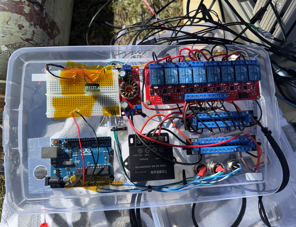

V1 electrical box (tupperware)

V2 electrical assembly (ESP32)
V1 switchbox

V2 Electrical box (ammo can)


